Service Provider - Half-Duplex VPN's
Cisco Half Duplex VRF’s (HD VRF’s) #
The other day whilst reading up on some SP topics I came across a rarely used function available on some higher end Cisco models called half duplex VRF’s (or HD VRF’s in some places).
I know it is quite a common thing to see in service provider topologies where you have a radius / virtual-template driven platform such as a DSL LNS etc but up until now I wasn’t aware that it can also be used on other platforms on regular (non virtual) interfaces.
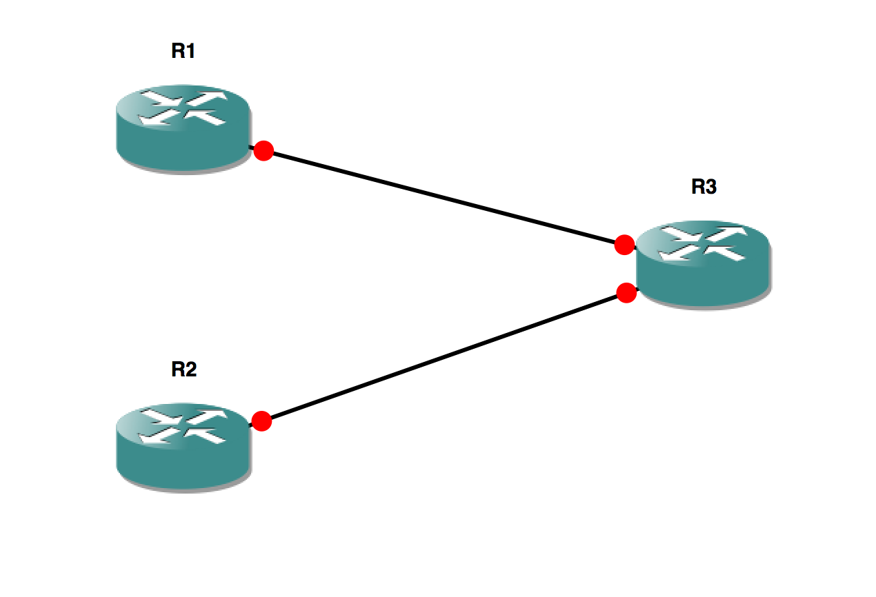
For the demo topology I am going to use a faily simple network of three 7200’s in GNS3. According to the Cisco documentation here this feature has been around since 12.4(20)T or 12.2(33)SRC for the SR train.
In the topolgy I am using R1 and R2 to emulate customer sites which will be a member of the same VRF on R3 which will play the role of our PE.
Although I am not going to actually use MP-BGP to create a VPNv4 topology you can still see the hub-and-spoke effect on the two devices.
One reason that this feature is used is that in a traditional MPLS VPN topology if you wanted a hub and spoke VPN you would have to have a seperate VRF on a particular PE for every ‘spoke’ site which although it may not be much of a problem if you only have a couple, imagine if you have 1000 spoke sites connected, the administrative work involved in create a new spoke VRF every time would become tiresome VERY quickly!
With HD VRF’s you have two different types of VRF in which you place an interface, you have the upstream which is typically where routes from your hub site will live (possibly just a default route) and you have the downstream which is where all hub routes are placed to be exported.
Due to the fact that only the upstream VRF is used for forwarding on the PE it means that although all the sites routes are in one place in the downstream VRF they are unable to forward traffic between sites (as seen below).
It should be noted that in the example I will be using the more modern VRF implementation that supports multiple address families, I will do another post on this later this week.
### Here is the basic config from R3 which defines both the upstream and the downstream VRF's, as you can see nothing special here.

vrf definition DOWNSTREAM
 rd 100:2
 route-target export 100:2
 route-target import 100:2
 !
 address-family ipv4
 exit-address-family
!
!
vrf definition UPSTREAM
 rd 100:1
 route-target export 100:1
 route-target import 100:1
 !
 address-family ipv4
 exit-address-family
We then define the usual addressing on the spokes/CE’s
## R1
interface FastEthernet0/0
 ip address 10.1.3.1 255.255.255.0
 duplex auto
 speed auto
!
ip route 0.0.0.0 0.0.0.0 10.1.3.3

## R2
interface FastEthernet0/0
 ip address 10.2.3.2 255.255.255.0
 duplex auto
 speed auto
!
ip route 0.0.0.0 0.0.0.0 10.2.3.3

## The static routes here are used for reachability to the loopback on R3
So that we have something to test to we will create a Loopback on R3 which would usually (if we were using more devices) live up at the hub site but for demonstration it is going to sit in the DOWNSTREAM VRF (but not using HD VRF’s).
interface Loopback0
 vrf forwarding DOWNSTREAM
 ip address 3.3.3.3 255.255.255.255
end
The configuration on the spoke facing interfaces is where we start to see the HD VRF’s used:
interface FastEthernet0/0
 vrf forwarding UPSTREAM downstream DOWNSTREAM
 ip address 10.1.3.3 255.255.255.0
 duplex auto
 speed auto
!
interface FastEthernet0/1
 vrf forwarding UPSTREAM downstream DOWNSTREAM
 ip address 10.2.3.3 255.255.255.0
 duplex auto
 speed auto
Now if the config is all correct we should be able to ping from spoke->hub but not from spoke->spoke….
R1#ping 3.3.3.3
Type escape sequence to abort.
Sending 5, 100-byte ICMP Echos to 3.3.3.3, timeout is 2 seconds:
!!!!!
Success rate is 100 percent (5/5), round-trip min/avg/max = 8/17/36 ms
R1#
R1#
R1#ping 10.2.3.2
Type escape sequence to abort.
Sending 5, 100-byte ICMP Echos to 10.2.3.2, timeout is 2 seconds:
.....
Success rate is 0 percent (0/5)
So there we go, with just two VRF’s on a PE device you can create a complete hub & spoke topology without allowing traffic to pass between spoke sites.
